Compensating inertia in force measurement


Dynamic forces are widespread in industrial force measurement. When measuring such forces, precision can be improved by compensating the forces produced by the force introduction components’ inertia. The following method description details how to compensate the inertia using the integrated acceleration sensors from the DR force transducer range. The benefit is that you need no prior knowledge of the mass or acceleration values.
The problem of mass inertia
In dynamic testing, acceleration of assembly components such as clamping tools or sample holders produces mass inertia effects. Alongside the desired test force Ftest, dynamic excitation produces an undesired inertial force Finert through the multiplication of the assembly components’ mass and acceleration. Finert distorts the measured force value Fmeas. For the force transducer, a distinction between force applied to the sample and undesired inertial forces is impossible without further modification.
Fmeas = Ftest + Finert
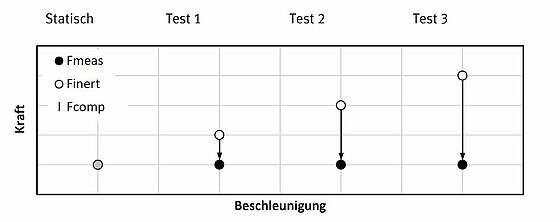
However, measuring the acceleration along the force measurement axis facilitates determination of the undesired force Finert and allows it to be compensated by applying an opposing, equal force Fcomp:
Fmeas = Ftest + Finert + Fcomp
Where Fcomp = - Finert will produce a correct measurement of the testing force on the sample:
Fmeas = Ftest
Mechanical model
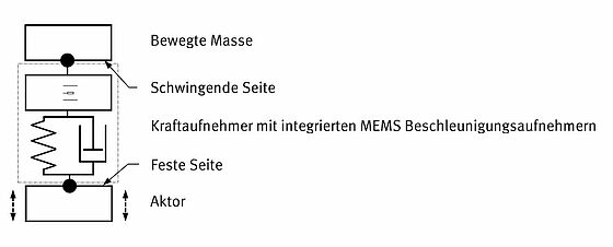
The model comprises three components: the actor (e.g. hydraulic cylinder), the force transducer with integrated MEMS acceleration sensors and the assembly components in the form of connected, moving masses (MEMS = microelectromechanical system).
- The assembly components (moving mass) need to be installed on the force transducer’s ‘oscillating side’.
- The force transducer’s ‘rigid side’ needs to be attached to the actor.
Basic test setup for compensation
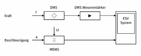
The strain gauges used in the force transducer are wired together to form a Wheatstone bridge and convert an applied mechanical load to an electric signal. Depending on your requirements, use a precision DMS measuring signal amplifier with an analogue or digital output signal. The system used for electric signal processing must be capable to determine and process the peak-to-peak amplitudes of the measured dynamic signal. Using the peak-to-peak amplitudes eliminates the influence of the various phase changes in the signals used for compensation.
In the DR force transducers, the acceleration sensors are located as close as possible to the force measurement axis. The MEMS components convert applied acceleration to an electric output voltage. The systems are radiometric, which means that the output voltage depends directly on the supply voltage. This makes a stable power supply imperative. Here, too, the measuring system needs to be capable of calculating the output signal’s peak-to-peak amplitude.
Determining compensation
The compensation parameters need to be determined taking into account the assembly components’ mass but without contact to the specimen. During the test, we require Ftest = 0.
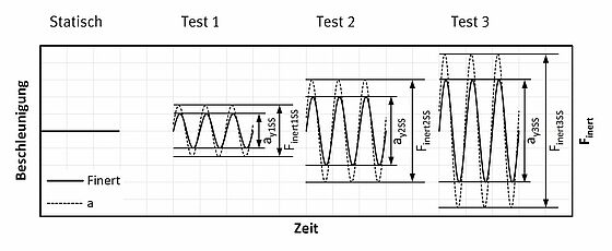
To identify the settings for Fcomp, excite the system using harmonic load cycles across the entire testing frequency range. When doing so, record the force transducer signal Fmeas, which under free oscillation is equivalent to the uncompensated inertial force Finert because there is as yet no contact with the sample. Also record the associated acceleration sensor signal. Conduct a test series with varying amplitudes and frequencies according to your requirements.
Example:
Description | Force | Acceleration |
|---|---|---|
Variable | FinertSS | aySS |
Unit (example) | V | V |
Force transducer with attachments, static | 0 | 0 |
| Test 1 | 3 | 2 |
Test 2 | 6 | 4 |
Test 3 | 9 | 6 |
Calculate the proportionality parameter for compensation.
In our example, this is: FinertSS = 3/2 · aySS
Depending on your test requirements (amplitudes, frequencies), it may be necessary to perform not only a linear correction but to also calculate the second and higher orders. Combine the force signal and acceleration signal according to:
Fcomp = - Finert
The result is Fmeas = 0 across the entire test range. The compensation ‘pulls’ the inertial forces back to the value of the desired dynamic force.
Once you have determined and applied the compensation settings, you can clamp the sample. The measured force Fmeas will no longer be affected by the undesired inertial forces.
« Back